CAD to Cut: Building a Reliable CAD/CAM and Nesting Workflow
By Brad Cairns
Published Updated
A laser cell is only as productive as the programs feeding it. In shops where the machine sits idle with the operator waiting, the first thing to examine is not programming talent but whether a standard route from drawing to released program exists. This guide sets out that route, the file problems that create avoidable delays, and a release checklist you can adopt as written.
Start here
Standardise three things and the programming queue becomes predictable: what a submitted file must contain before anyone starts work on it, how geometry is cleaned and nested, and what must be true before a program is released to the machine. Treat programming as a scheduled production stage with its own measured capacity, not as something squeezed in around quoting.
File intake: refuse ambiguity early
A file problem is least expensive to fix before it enters the queue. Define a single intake standard and apply it to customer files and internal drawings alike.
- One geometry file per part, named to the part number and revision.
- Units and scale stated explicitly, not inferred.
- Material grade, thickness and finish stated on the drawing or the job, not assumed from a previous order.
- Bend lines, tapping, countersinks and any downstream operation identified — cutting geometry alone is not a manufacturing definition.
- Critical features and datums identified, so nesting and inspection agree with each other.
Where a customer cannot supply this, capture the answers in writing at quoting time. Feasibility problems found at the machine are expensive; found at quoting they are a conversation.
Material and thickness conventions
Nesting and cut-parameter selection both depend on a shared, unambiguous way of describing material. Two conventions worth fixing in writing before they cause a misnest:
- One naming scheme for grade and finish. If the shop stocks the same grade from two mills under different mill-cert names, map both to a single internal identifier before it reaches nesting software, or duplicate stock records will hide available inventory.
- Thickness stated as nominal and as measured tolerance band, not as a single number. Actual sheet thickness varies within a mill's tolerance, and a program tuned for nominal thickness can behave differently at the edges of that band. Where a job is sensitive to this, note the measured thickness on the traveler rather than relying on the mill certificate alone.
- A fixed list of thicknesses the shop actually stocks, so programmers are not guessing at what's on the shelf and estimators are not quoting a thickness that requires a special order without saying so.
These conventions belong in the same document as the intake standard, not as informal knowledge held by one long-tenured programmer.
Geometry cleanup
Flat-pattern files tend to arrive with a recurring set of defects. Build the fixes into a routine rather than solving them creatively each time.
| Defect | Symptom downstream | Fix |
|---|---|---|
| Open contours | Toolpath will not generate, or cuts as an open line | Close all profiles; verify continuity |
| Duplicate or overlapping entities | Double cutting, burn-through, wasted time | Purge duplicates before nesting |
| Spline-heavy geometry | Jerky motion, slow travel, poor edge | Convert to arcs and lines within tolerance |
| Text or construction geometry on cutting layers | Unwanted cuts | Layer discipline; a strict cutting layer convention |
| Features smaller than the process supports | Taper, dross, blowout | Flag at intake; validate with a sample |
| Missing bend relief | Cracking or distortion at forming | Resolve with engineering before release |
Layer conventions do a surprising amount of work here. Agree once what layer holds cutting geometry, what holds etch or marking, and what holds reference information — then enforce it.
Lead-ins, lead-outs and cut sequencing
These are generic process concepts, but they are where a competent program separates itself from a merely valid one.
- Place lead-ins where a witness mark is acceptable, away from critical features and mating edges.
- Size lead-ins for material and thickness; a lead-in appropriate for thin material may not pierce reliably in thick.
- Sequence cuts so heat is distributed rather than concentrated in one region of the nest, particularly for thin material and enclosed shapes.
- Sequence so small parts release into a supported position instead of tipping into the path of the head.
- Cut internal features before the outer profile so the part is still held while the precision features are made.
Nesting decisions worth standardising
- Yield versus handling. The tightest nest is not the right nest if the parts are difficult to separate or the skeleton becomes unmanageable.
- Common-line cutting. Sharing a cut between adjacent parts saves time and material where edge tolerance and part support allow it. Decide when your shop permits it rather than leaving it to individual judgement.
- Part spacing for heat-sensitive work. Give thin material and long slender parts more room.
- Grouping by material and thickness. This is a direct lever on changeover count, so nest with the machine's schedule in mind, not just the individual job.
- Repeat parts. Save the nest and the program. A repeat part should approach zero programming time.
Remnant tracking
Remnants are inventory. Untracked, they become a pile nobody trusts and material yield quietly falls. A workable minimum: label every remnant above a defined size with material, thickness and dimensions when it leaves the machine, store it where programming can see it, and make checking remnant stock a step in the nesting routine rather than an afterthought.
Revision control and program release
Adopt one rule: the machine only runs programs from the released location, and released programs are not edited in place. If a change is needed, it becomes a new revision. Combined with part-number-and-revision file naming, this closes off an expensive failure mode: cutting a superseded revision at quantity.
Keep post processors under the same control. A post processor is a configuration item; when it changes, previously released programs may no longer behave identically. Record the post processor version alongside the program, and confirm the correct post processing route for your exact machine control with your supplier rather than reusing one from another machine.
Job travelers and identification
Identification discipline earns its place in a mixed-part shop. A printed traveler with part number, revision, material, thickness, quantity, nest identifier and downstream route lets the operator verify what they are about to cut and lets sorting happen without guesswork. If you already use barcodes elsewhere in the shop, extending them to nests and travelers is a natural step. Whether the machine or its software can consume that data directly is a per-machine question to confirm.
The operator feedback loop
A programmer who seldom visits the floor can release programs that are technically correct and awkward to run. Close the loop deliberately: a short weekly review of programs that caused problems, with the operator present. Capture the outcome as a change to the standard rather than as a note to one person.
File-release checklist
Nothing goes to the machine until every line is true.
- Part number and revision on the file and on the traveler.
- Material, thickness and finish confirmed against the job.
- All contours closed; duplicates purged; layers correct.
- Geometry converted to arcs and lines where splines were present.
- Feature sizes checked against process limits for that thickness.
- Lead-ins placed away from critical and mating features.
- Cut sequence reviewed for heat distribution and part release.
- Nest checked against remnant stock before consuming a full sheet.
- Parameters and compensation values match the material and thickness.
- Correct post processor version used and recorded.
- Quantity verified against the order.
- Program saved to the released location; no local edits.
- First-article requirement flagged where applicable.
Handoff between engineering and the shop floor
In a CAD-to-cut workflow, failures at the handoff points tend to cost more than failures inside any single step, because no one owns catching them. Three handoffs deserve explicit ownership rather than an assumption that "someone" checks them:
- Engineering to programming. The design file is not automatically a manufacturing file. Confirm that the person releasing a drawing has flagged tolerances, bend allowances and material substitutions before it reaches nesting, rather than leaving programming to infer intent from geometry alone.
- Programming to the floor. The traveler and the released program must agree with each other and with the physical material staged for the job. A mismatch caught by an operator before the first pierce is a delay; the same mismatch caught after a full sheet is cut is scrap.
- Floor back to engineering. When an operator adjusts a parameter or a lead-in placement to solve a real problem on the machine, that fix needs a path back into the released program and, where it reveals a design issue, back to engineering. Without a defined path, the same problem gets solved locally on the machine every time the job runs, and the fix does not reach the file.
Assigning a name — not a department — to each handoff is what makes it durable. "Engineering owns the flag" and "programming owns the release" are different statements from "the team handles it," and only the first kind survives staff turnover.
Measuring programming as capacity
Track programming hours per released job, split between new and repeat parts, and compare programs released per day against programs consumed per day. If consumption exceeds release, programming is your constraint and no machine change will help. Our workflow article covers the wider measurement exercise, and the quality guide explains how datums set in CAM should carry through to inspection.
Want to check how your existing files behave on a specific machine? Bring a few real drawings to a demo rather than a sample part.
See the machines behind the article
Browse the full Mekotek product brochure, or book a live demo and watch a Mekotek fiber laser cut your own material.
Related Articles
Fiber Laser Welding Guide: Process, Fit-Up and Power Selection
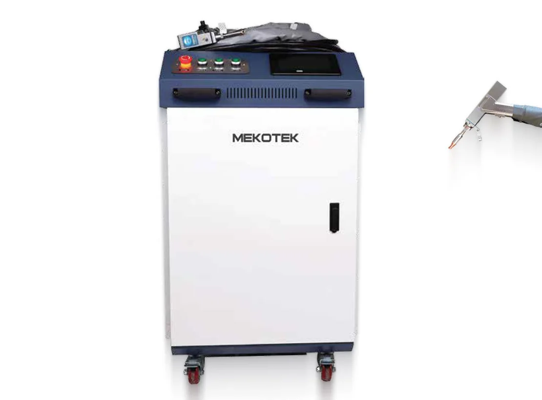
Handheld fiber laser welding trades broad heat input for narrow, concentrated heat — and it demands tighter fit-up than arc welding to deliver that benefit.
Tube Laser Cutting: Dedicated Machine or Sheet + Tube Combo
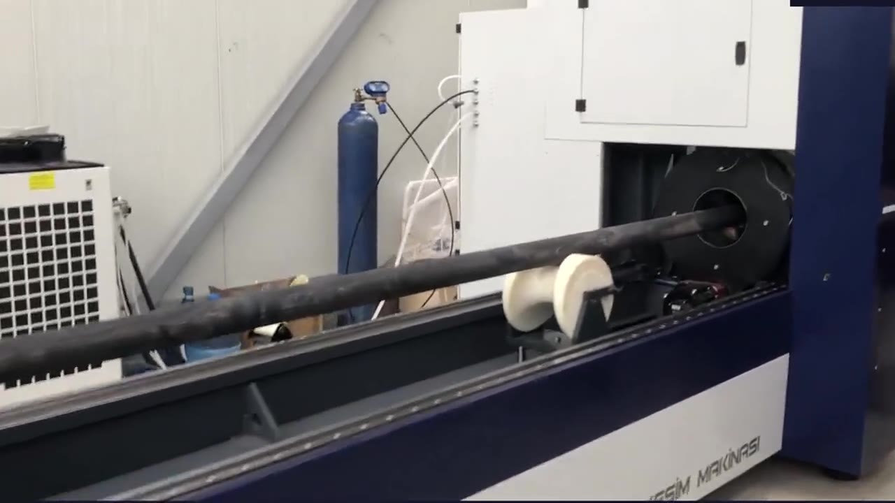
How round, square, rectangular and open-profile tube is cut on a laser, and how to decide between a dedicated tube machine and a sheet-plus-tube combo.
Material Handling Around a Laser: From Manual to Automated
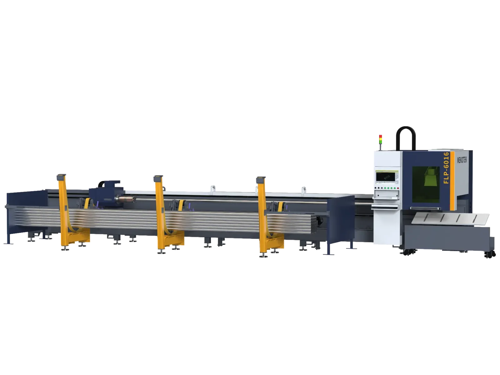
The laser spends part of every shift waiting on metal to be moved, not cut. A stage-by-stage look at handling sheet and tube, and when automating it is justified.